POWER RAIL CONFIGURATION
Introduction
Proteus provides a special dialogue form for viewing and/or modifying the power supply connectivity within your designs. This allows you to create one or more power supplies and then to specify bindings between power supply nets and the actual power supplies. This is particularly useful for handling designs in which there are ICs with hidden power pins as you can then determine exactly what power nets there are in the design and also specify interconnections between them where appropriate.
Each power supply has associated with it a Voltage which is used during simulation, and a Routing Class which determines the PCB design rules that will be used for all nets bound to the power supply.
Dialogue Form
The Power Rail Configuration dialogue form carries two tabs. The Power Rails tab holds the supplies and their net bindings. The Net Class tab holds the PCB net class editor, placed here so that a routing class for a rail can be created without leaving the schematic.
The Power Rails tab is divided into two sections. The top section, labelled Power Supplies, allows you to create, edit and delete named power supplies: the Name drop-down selects the supply you are working on, the New, Rename and Delete buttons maintain the list, and the Voltage and Class fields carry the selected supply's voltage and routing class. The bottom section allows you to view and manipulate the power nets that are bound to each power supply. Unconnected power nets on the left lists every power net that is not yet bound to a supply, and the Add and Remove buttons move nets between that list and the Nets connected to list on the right. In a correctly configured design, the Unconnected power nets list should be empty.
Context sensitive help is provided for the individual controls on the form.
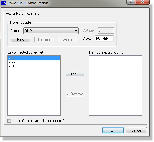
Power Rail Configuration Dialogue form
See Net Classes in the PCB Layout manual for what the Net Class tab controls do.
Power Rail Bindings and Design Connectivity
Where more than one net is bound to a power supply, these nets will then be treated as interconnected for both simulation and PCB layout. The Power Rail Configuration dialogue form thus provides a means to specify interconnections between power nets that have been created by the hidden power pins of TTL and CMOS logic ICs and NMOS microprocessor parts. In particular, some parts have pins VCC/GND and some have VDD/VSS and it is very common to need an interconnection between VCC/VDD and VSS/GND.
Notes
- If you name a net with the same name as the power supply it will bind to the power supply. For example, creating a supply called CHASSIS and then naming a net CHASSIS would automatically bind the net to the supply.
- A power terminal denoting a voltage (+<num> or - <num>) will automatically create a power supply with that voltage. The prefix is required to avoid ambiguity.
- If two named power supplies end up wired together, the netlist compiler reports that the power rails are interconnected in the net concerned. Bind both nets to a single supply rather than wiring the supplies together.
- In a simulation, a supply that you created in the dialogue form takes its net name from its voltage, so a 3.3V supply appears in the simulation netlist as +3.3V, and a supply set to 0V is connected to GND. Supplies placed on the schematic, and the rail names used for PCB layout, are unaffected: they are used exactly as you named them.
Default Power Rail Configuration
To make life really simple for new users, Proteus provides a default power rail configuration. This is specified in the file PWRRAILS.INI as follows:
| POWER SUPPLY | VOLTAGE | NET BINDINGS |
NET CLASS |
|
VCC/VDD |
+5.0 |
VCC/VDD |
POWER |
|
VEE |
-5.0 |
VEE |
POWER |
|
GND |
0 |
GND, VSS |
POWER |
When you create a new design, these rules will be applied automatically. Note also that the default power supplies and their associated bindings cannot be renamed or deleted unless you clear the Use default power rail connections? checkbox on the Power Rail Configuration dialogue form.
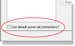
The Use default power rail connections? checkbox
Ticking the checkbox again resets the power rail configuration to the defaults specified in PWRRAILS.INI, discarding any supplies and bindings you have set up. You are asked to confirm before the reset is applied.
Note that the GND power supply can never be renamed or deleted and its voltage is fixed at 0V. You can, however, edit the routing class.
On Schematic Power Rails and Bindings
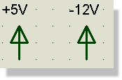
Power Rails specified on the schematic
You can also specify power supplies and power rail bindings on the schematic. On-schematic power supplies are created by placing power terminals with labels such as +5V or -12V.
Power supplies created in this way cannot be renamed or deleted from the dialogue form and the voltage cannot be changed. You can, however, still edit the routing class. Note also that power terminals of this type create both a power supply and a power net so you will also see a fixed binding between the +5V net and the +5V supply, for example.
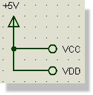
On Schematic Power Rail Bindings
You can also specify on schematic net bindings. For example, if you wanted to connect VCC and VDD to +5V on the schematic you would draw wiring that interconnected logical terminals labelled +5V, VCC and VDD. Note that, in this case, any hidden VCC and VDD pins would acquire the +5V supply as well.
Legacy Designs
Designs created with old Proteus versions prior to 6.6 will not contain power rail configuration data and will load with the Use default power rail connections? checkbox cleared.
To enable the power rail configuration features for old designs, you should visit the Power Rail Configuration dialogue form and then tick the Use default power rail connections? checkbox. At this point, the power rail configuration features will be enabled, and you must then ensure that all power nets are bound to a power supply.
See Also: